Invest in solar power for affordable and clean energy supply
 Ekol Logistics
Summary
Companies can develop rooftop solar power infrastructure to cut emissions and achieve energy independence
Context
Inspired by UN SDG 7 (Affordable & Clean Energy) and in line with the carbon neutral targets of the EU Green Deal, Ekol continues to invest in renewable energy. The company plans to invest in solar power plants for all its facilities where roofing infrastructure and environmental conditions permit. Lotus is the first facility in which Ekol invested in a solar power plant, and the company continues to conduct feasibility studies for 7,999 MWh solar power installation projects at other facilities, including its Kardelen, Orkide, and Lilyum facilities. Once all four projects are implemented, Ekol expects its Scope 2 emissions to decrease by 67%.
Solution
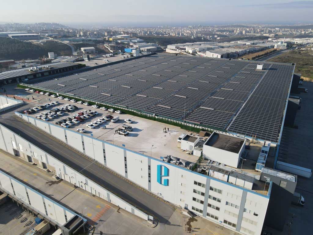
Following a feasibility study, Ekol installed 39,830 m2 of solar photovoltaic panels with a collective power of 5,589 kWp on the membrane roof, carport, and walkway canopy of its Lotus facility. The power plant has an observation, tracking, and controllable monitoring system at the PV module level.
The Lotus solar power plant, which is the logistics industry's largest solar panel project on a membrane roof, uses panels with optimizers and rapid shutdown systems. In addition to avoiding damaging the roof during installation, restrictions in system construction selection due to static calculations, weather conditions affecting the installation time, and exchange rate (electricity prices in TL, investment in USD) were among the difficulties overcome.
The energy produced by the solar power plant will supply the current energy needs of the Lotus facility, with excess energy returned to the grid. Ekol plans to offset the energy supplied to and received from the grid on a monthly basis.
General Information
Location: Gebze/Kocaeli (Turkey)
Solar Potential of the Region: 6,000-6,500 kWh/sqm/year
Roof Area (capable of accommodating solar panels): 39,830 sqm
WH Main Roof: 35,800 sqm
Office Roof: 2.260 sqm
Carport: 1,370 sqm
Walkway Canopy: 400 sqm
Site Transformer Capacity: 5,200 KVA (1,600 + 1,600 + 2,000)
Lotus Energy Consumption (2021): ~9,250 MWh/Year
Technical Specifications
Solar Capacity to be Installed (AC Output): 4,200 kWe
Number of Inverters: 42 Units x 100 kWe/unit
Solar Capacity to be Installed (DC Output): 5,589.25kWp
Number of PV Panels: 14,250 units x 395 Wp/Unit
Energy Generation by Solar System: 6,148 MWh/Year (in first year)
Specific Production: 1,100 kWh/kWp-year
Solar Panel Angle: East-West (10-15 degrees slope)

Impact
Climate impact
Targeted emissions sources:
Scope 2
Decarbonization impact:
The Lotus solar power plant reduces annual CO2 emissions by 3,100 tons, including the reduction of NOx, SOx and PM emissions, which has a positive impact on air quality and overall public health.
Business impact
Benefits
The project’s environmental, social, and economic impacts are measured and reported annually, which increases awareness among customers and encourages other companies to take similar action.
The facility is expected to save approximately 600 thousand USD in electricity costs annually
Costs
The investment costs for the project, which was completed in approximately 1 year time, are approximately 4 million dollars. This includes the main roof area panels and the carport-walkway canopy area panels.
The return on investment is expected to be less than seven years. The amount of energy produced will be used directly for self-consumption as much as the facility's instant needs. Excess energy will be given back to the grid.
Impact beyond climate and business
Co-benefits
Considering green transformation policies in energy all over the world, it is predicted that the renewable energy sector will create new job opportunities. With this project investment, EKOL created employment, with corresponding positive economic impact, in the renewable energy sector during the pandemic period.
Implementation
Typical business profile
The solution is suitable for most businesses that have a membrane roof which is feasibly suitable for solar photovoltaic panels.
Approach
The Lotus facility’s roofing system was already designed to accommodate the load of solar panels, but this is something that needs to be considered in advance.
1. Roofing Material: Membrane roof
The most important features of membrane type roofs are their low slopes and the fact that the roof surface is completely insulated against liquid penetration, ensuring full impermeability.
Key Properties:
550 mm distance, in case of turbulence near the parapets
Confirmation of resistance to snow and wind loads when fastening PV modules from their short sides
Wind tunnel tests
Preventing interference to the roof’s drainage system
Using existing membrane welding points for load
Certificates of screws used
Using the same brand and model patch membrane throughout the project
Sensitivity of junction points and not screwing
Lack of open end of the membrane patch in the direction of water drainage
Important considerations for roof PV Systems
Sealing
Reliability
Static compliance
Minimum cost
High production/PR
Optimizing area
2. Carport and Walkway Canopy
Carport | Walkway Canopy | |
Area | 1,370 sqm | 400 sqm |
PV Modul | 684 units * 395 Wp | 196 units * 395 Wp |
DC Power | 270.18 kWp | 77.42 kWp |

3. PV Modules Direction
The roof of the Lotus Plant is a membrane roof filled with rockwool. The roof slope is 2%, therefore, if the placement of the PV modules is made at the same slope as the roof:
Dust and snow accumulate on the PV modules
Resulting in:
Efficiency/production/PO ratio falling
PV modules overheating
To address these challenges, the project team decided to change the angle and direction of the solar panels.
Option 1: South Direction: The surfaces of the PV modules are turned to the south and angled at >10°, which is the most efficient direction. Distance is also left between panels to minimize a shadow effect, resulting in fewer panels on the roof area.

Option 2: East-West Direction: The surfaces of the PV modules are placed back-to-back in an east-west direction to follow the sunrise and sunset, while the system is angled >10°. In this configuration, PV modules do not shade each other, which allows the roof area to be used more efficiently.

4. Mounting System
Model: FLATFIX WAVE PLUS
Ideal for large-scale projects
Suitable for large, next-generation solar panels up to 1149 mm wide
Dual setup (east-west)
Large panel fields (40 × 40)
Pitch length of 2300 mm/2460 mm
Angle of inclination 10°
QUICK, ERROR-FREE INSTALLATION
No tools needed
Easy to disassemble for panel maintenance
Integrated cable management
SAFE AND RELIABLE
Integrated bonding
Panel clamped on the long side, minimizing risk of panel damage
Low point load
Roof supports with movable connectors, preventing damage to the roof
Meets strictest corrosion requirements
Extensively tested and developed in accordance with various international safety standards
Approved on compatibility by PV manufacturers
5. Fixing System (OMG+Ballast)
A ballasted system is generally preferred to avoid puncturing the roof. Systems where the ballast is statically insufficient and applied together with other techniques are called hybrid systems.
A hybrid system best suited the Lotus facility roof, considering it’s a membrane with insulation sensitivity and static compatibility.
Surface Preparation
Before applying any treatment to the membrane, there are some points to be considered.
Cleaning, placement, suitable weather conditions
Anchor Placement
The anchor is fixed on a hanger screw, then installed with additional fixing screws by removing the flange.
The patch membrane is fixed by welding it to the roof membrane.


6. Inverter System
Producer: Solaredge Inverter Model: SE82.8K
Maximum AC Power Output: 82,800 VA
Maximum DC Power Input (Inverter/Unit): 111,750/37,250 W
Optimizer Model: P801
7. Rapid Shut-down & Efficiency Optimization
Power Optimizer Key Benefits:
Per-module Maximum Power Point Tracking (MPPT), with one Power Optimizer per two modules using commercial Power Optimizers
Superior efficiency (99.5% peak efficiency, 98.8% weighted efficiency)
Mitigates all types of module mismatch-loss, from manufacturing tolerance to partial shading and aging
Designed for extreme environmental conditions
Advanced, real-time performance measurement
Automatic module DC voltage shutdown for installer and firefighter safety
8. Monitoring
The monitoring platform provides enhanced PV performance monitoring and yield assurance through immediate fault detection and alerts at the module, string, and system level.
No hardware or wiring is required to transmit data from the power optimizers to the inverter. The monitoring sensors and transmitters are built into the SolarEdge power optimizer and solar inverter, and measurement data is transmitted over the regular power lines.
Stakeholders involved
Project Lead: Ekol Logistics
Company functions: Engineering department
Main providers: All project stages such as project design, power plant installation, system commissioning and TEDAŞ processes follow-up were carried out by CW Enerji.
Key parameters to consider
Solution maturity: Well known, established technology (see Switch to solar energy with rooftop photovoltaics)
Lifetime: Minimum 25 years
Technical constraints or pre-requisites: Roof membrane suitability and feasibility
Availability: Available for all sectors, not recommended in areas with heavy rainfall
Implementation and operations tips
Photovoltaic solar panels do not pose fire risks on their own. However, if a photovoltaic installation fails, some of its components can become flammable. The main source of solar panel fires is related to poorly assembled connectors. In terms of components, the main cause of fire is associated with a faulty junction box that overheats. For example, incorrectly joining connectors can cause an electric arc, which means significant heat dissipation. This may cause overheating and fire.
In the event of a fire, intervention requires fire extinguishers suitable for electrical systems. But if the fire grows and firefighters need to intervene, the energy production of the panels must be cut off. For this purpose, Ekol plans to use power optimizer solutions in its solar power plant project.